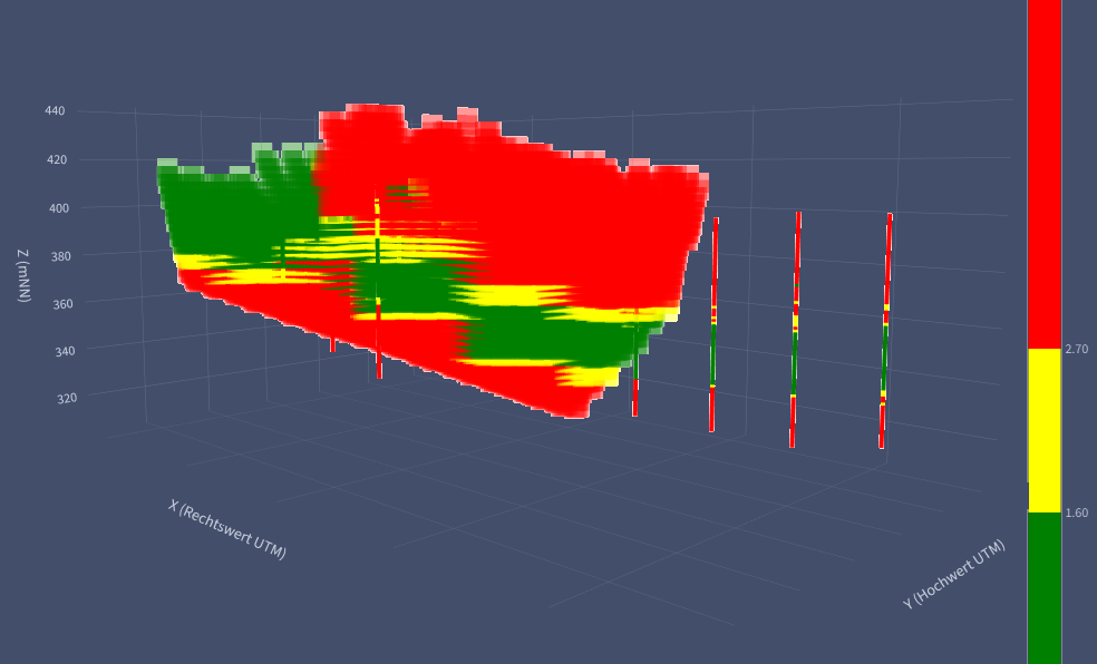
Drill data becomes a block model carrying the quality parameters that matter for your material — block by block, spatially interpolated.
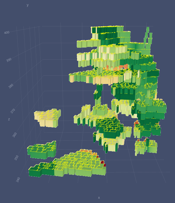
Extraction fields that hit a given target tonnage while staying inside your quality requirements. Edge blocks are counted pro rata, not in full.
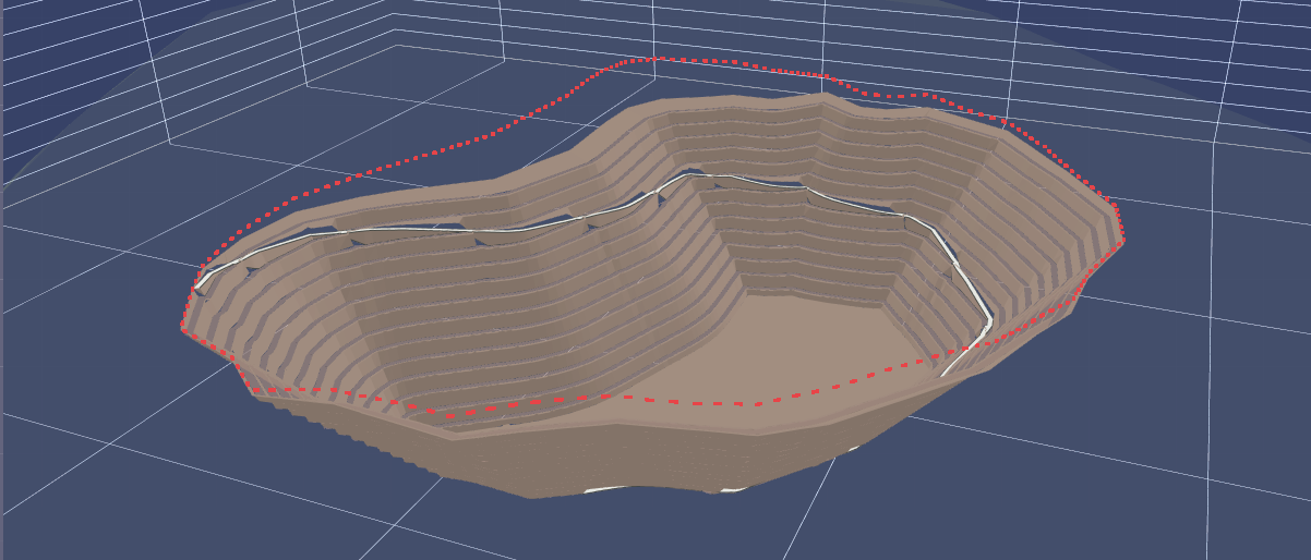
The open pit on your actual terrain: benches, faces, berms and a ramp — computed for every interim stage.
Area, volume and tonnage per stage as a report — plus the geometry as DXF that can be processed straight on in your CAD or by your surveyor.
Drill data is spatially interpolated and condensed into a block model. The compute core is written in Rust — so models with tens of thousands of blocks take seconds. Block size, grid rotation and density stay fully adjustable.
Blocks are grouped into contiguous extraction clusters that reach a target tonnage while staying inside the quality requirements. Edge blocks count only with their actual share. Counted in full, volume and tonnage run some 6 % too high; on more fragmented models, considerably more.
Terrain survey and extraction boundary become the stepped pit — bench by bench, with faces, berms and an optional ramp. One hard rule applies: an extraction bench is created only where the terrain lies above it. Toes are clipped against the contour at their own elevation. That is the difference between a parametric sketch and a pit you can actually build.
You change the face angle, bench height or target tonnage — the result is there in seconds, not at the next meeting.
16 seconds · no sound
The programs were developed by me. If your operation needs an analysis that does not exist yet, it gets built — instead of bending your question to fit someone else's software.
| Terrain | LAS · LAZ · DXF · TXT · XYZ — point cloud from drone flight, laser scan or your last survey |
| Boundary | DXF · Shapefile · TXT — several extraction fields with their own names, separable per bench |
| Drill data | CSV with coordinates and assay values — columns are mapped on import, no fixed template needed |
| At a pinch | A boundary as PNG or JPG from a scanned map can be read in as well |
| DXF | 3D lines of toe and crest edges plus the triangle mesh as 3DFACE — opens in AutoCAD, BricsCAD, Civil 3D |
| CSV | Report with area, volume and tonnage per interim stage — drops straight into your costing |
| Views | 3D view of the pit on the terrain, stage by stage — plus the plan view over map or aerial imagery |
| On request | Further formats such as SHP or LAS, and preparation as an annex for operating plan and permitting documents |
Block model with over 22,000 blocks, extraction clusters by quality, pit geometry including ramp.
Several quarry extensions built in quarry mode, terrain intersection against contours, DXF handed to the surveyor.
Just name your project. From publicly available data you get a first draft plan before we talk about an assignment.